When specifying a needle valve for an industrial instrumentation application, technical attention is almost always focused on pressure ratings, materials, and connection types. The bonnet—the component that houses the stem, manages external sealing, and determines actuation behavior—is often treated as a secondary detail. This is a mistake that is paid for in the field.
The bonnet is the primary barrier between the process fluid and the external environment. Its design influences operator safety, valve service life, ease of maintenance, and compliance with increasingly stringent fugitive emissions requirements. Understanding it in depth is essential for anyone specifying, purchasing, or installing needle valves in critical industrial contexts.
What is the Bonnet and Why is it a Critical Choice
The bonnet is the structural element that closes the upper part of the valve body, housing the stem and its sealing system (packing). It must simultaneously fulfill three fundamental functions: contain the process pressure, allow the stem to be actuated with acceptable operating forces, and maintain external tightness throughout the valve’s operational life, under the temperature and pressure conditions predicted for the service.
In an instrumentation application that may operate at pressures up to 10,000 or 15,000 PSI, with potentially toxic or flammable fluids, a bonnet failure is not a maintenance inconvenience: it is a safety event. For this reason, bonnet design cannot be isolated from operational condition analysis.
Key Functions of the Bonnet
Blow-out Proof Stem
The blow-out proof design of the stem is arguably the most critical feature regarding operator safety. In a poorly designed valve, excessive unscrewing of the handle or a sudden overpressure can cause the stem to be ejected along with the pressurized process fluid.
A properly designed bonnet includes a mechanical restraint system—typically a shoulder on the stem thread or a retaining ring—that physically prevents the complete extraction of the stem from the valve during normal operation. This feature must be verified through documentation during the supplier qualification phase and cannot be substituted by operating procedures.
Non-Rotating Stem Tip
The distinction between the stem and the tip may seem like a minor construction detail. In reality, it is one of the elements that most heavily impacts seat seal durability.
In valves where the stem and tip are machined from a single piece, every closing operation generates a rotating movement of the tip against the metal seat. The practical effect is progressive friction and wear of the seat, which over time compromises tightness. The practical result is increased maintenance frequency and, in critical applications, the risk of undetected leaks under low differential pressure conditions.
The non-rotating stem tip—physically separated from the stem and free to rotate independently—eliminates this wear mechanism. The tip seats itself using pure axial movement without tangential friction, preserving the seating geometry for a significantly higher number of actuation cycles.
Multiple Sealing
A well-designed industrial bonnet incorporates at least two independent sealing points: a primary seal, which performs the normal containment function, and a secondary seal, which takes over if the primary seal degrades. This redundancy is particularly relevant for toxic or flammable fluid applications where even minimal leakage to the atmosphere is unacceptable.
The presence of a secondary seal also allows for the safe planning of packing maintenance without having to isolate or depressurize the entire measurement loop in an emergency.
Bonnet Types: Characteristics and Applications
Standard Screwed Bonnet
The screwed bonnet is the most common configuration for general instrumentation applications. The bonnet body is threaded into the valve body, and tightness is guaranteed by the combination of the threads and a backing gasket.
It is the optimal solution for moderate temperature and pressure services, where maintenance requirements do not involve frequent adjustments to the packing and where thermal cycles are not particularly severe. Its design simplicity translates into low cost and streamlined inventory management.
The main limitation of the screwed bonnet emerges in applications with repeated thermal cycles: temperature variations generate differential expansion and contraction between the bonnet and body, which over time can loosen the thread preload and compromise tightness.
- Anti-tamper variant: A specific version of the screwed bonnet features an external geometry that prevents operation without a dedicated tool. It is used in applications where safety procedures require restricted access to instrumentation valves, typically in chemical and petrochemical plants with structured Lockout/Tagout (LOTO) protocols.
- Lockable variant: Allows the application of a padlock to prevent valve operation. It serves a similar function to the anti-tamper version but utilizes a removable locking system that retains operational flexibility.
OS&Y Bonnet (Outside Screw & Yoke)
The OS&Y design represents a qualitative leap forward from the standard screwed bonnet in terms of functionality and operational lifespan. The yoke—a rigid structure anchored to the bonnet—supports the stem nut and houses the external thread that transforms the rotating movement of the handwheel into axial movement of the stem.
The fundamental benefit is that the threaded section of the stem never comes into contact with the process fluid. In traditional needle valves with internal threads, the fluid progressively erodes and corrodes the thread, generating two problems: an increase in the force required to operate the valve and the risk of wear that compromises correct plug positioning.
In the OS&Y design, the thread is completely outside the pressure zone. This ensures that the stem moves with consistent ease throughout the valve’s life, regardless of the nature of the process fluid, and that there is no thread corrosion due to fluid contact.
An additional operational advantage is the ability to visually and tactually verify the valve position (open or closed) via the rising stem, without having to interpret the position of the handle.
The OS&Y bonnet is also available in a compact version—where the yoke is integrated within a reduced footprint for installations on instrumentation panels where vertical space is a constraint—in a lockable version, and in an API 602 variant for applications requiring compliance with this specific standard.
Bolted Bonnet
The bolted bonnet is secured to the valve body by a separate flange/bracket with bolts. This configuration offers the highest mechanical strength for the body-bonnet joint, superior to any screwed solution, and maintains sealing preload even in the presence of repeated thermal cycles or dynamic stresses.
It is the preferred solution for the most severe applications: high pressure combined with high temperature, services with significant thermal cycles (e.g., superheated steam), cryogenic applications where the temperature differential between operating conditions and the environment is extreme, and all cases where the reliability requirement of the body-bonnet joint leaves no room for uncertainty.
In qualification tests according to the most stringent standards—such as the PR2F test, which verifies joint tightness under combined pressure and temperature cycles—the bolted bonnet guarantees superior performance compared to screwed alternatives.
Extended Bonnet
The extended bonnet is a specific engineering solution for the two thermal extremes of industrial service: cryogenic and high-temperature applications.
The principle is simple and effective: by increasing the length of the bonnet, the sealing system (packing) is moved away from the source of extreme heat or cold. Along this extended path, the fluid warms up (in cryogenic cases) or cools down (in high-temperature cases) until it reaches a temperature at which the packing can operate under optimal functional conditions.
- For cryogenic applications—LNG, liquid nitrogen, liquid oxygen, liquid helium—temperatures below -100°C render standard sealing materials completely unusable. The extended bonnet allows the packing to work in a zone where the temperature is compatible with elastomers or modified PTFE, ensuring tightness without requiring special cryogenic materials for the packing system.
- For high-temperature applications—steam service, processes at temperatures exceeding 250–300°C—heat conducted from the fluid through the stem rapidly degrades standard packing elastomers. The extended bonnet keeps the sealing zone at temperatures compatible with the materials used, preserving sealing integrity for its entire intended service life.
The length of the extended bonnet is dimensioned based on the fluid temperature, the thermal conductivity of the stem material, and the maximum allowable temperature for the sealing system. Common versions for LNG applications feature extensions from 50 mm to 80 mm, with lockable versions specifically designed for the operational requirements of liquefied gas plants.
Color Coding: Visual Safety in the Field
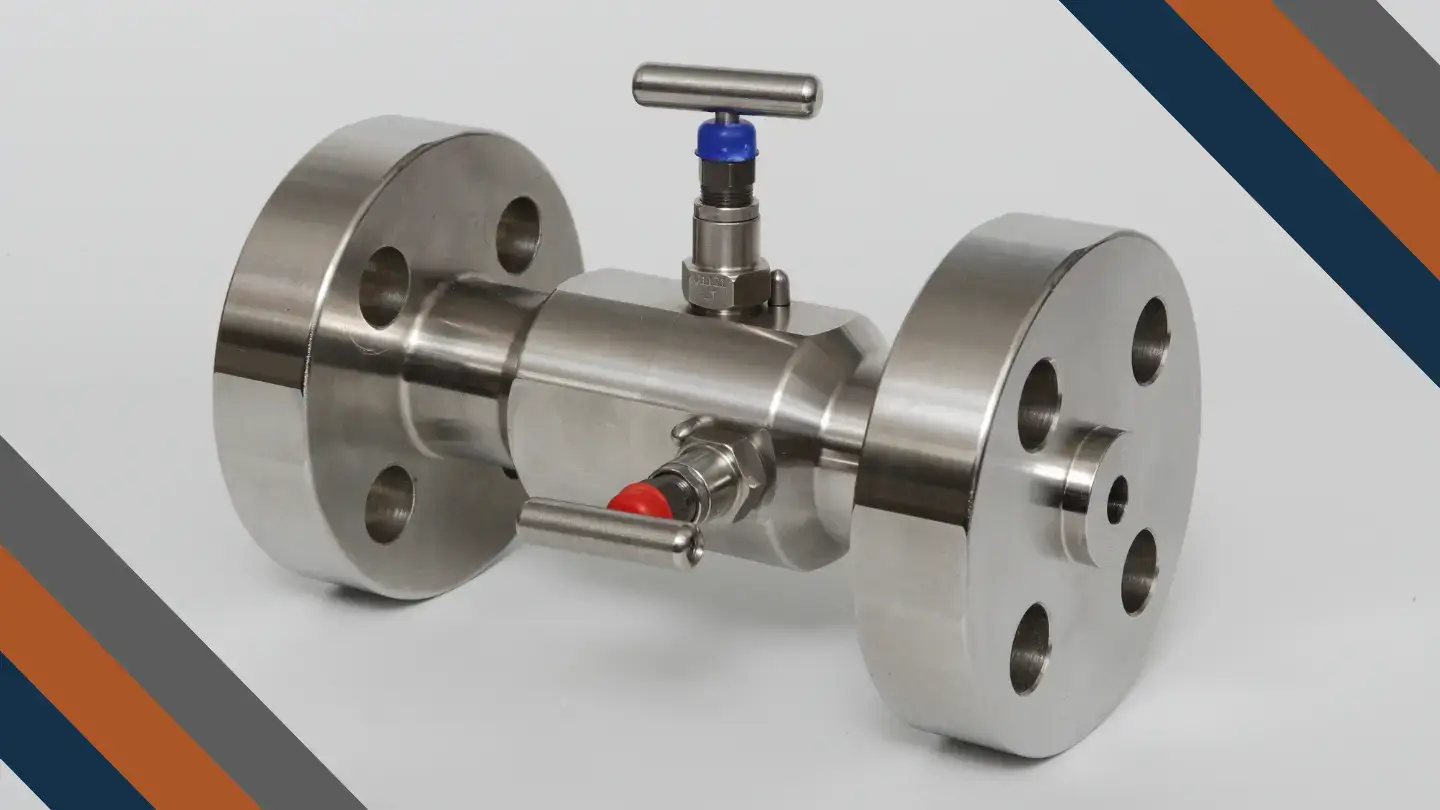
In instrumentation manifolds, individual valves are color-coded through the bonnet cap:
- Blue identifies isolation valves (isolate/block), which separate the instrument from the process line. These valves must remain open during normal operation and are closed to isolate the instrument during maintenance.
- Red identifies vent valves, which allow depressurization of the instrument cavity prior to removal. They must remain closed during normal operation and are opened only after the isolation valves have been shut.
- Green identifies equalizing valves (equalize), found in 3, 4, and 5-valve manifolds for differential pressure instruments. They connect the two sides of the transmitter for zero calibration or to verify the absence of internal leaks.
This visual system is not an aesthetic convention: it is an element of operational safety. In plants where multiple operators work on the same measurement loop, often under standardized procedures and low visibility or operational stress conditions, immediate color identification reduces the risk of incorrect operating sequences that could damage the instrument or create hazardous conditions.
Bonnets and Fugitive Emissions Compliance
Fugitive emissions requirements have become one of the most critical qualification criteria in instrumentation valve specifications, particularly within the framework of European regulations and international oil & gas major technical specs.
The fugitive emissions test according to ISO 15848-1 (type approval) verifies bonnet tightness through mechanical and thermal cycles using a test gas (helium or methane), measuring the gas concentration near the packing with high-sensitivity detectors. The resulting classification (from CO1 to CO3 for tightness class, and from AH to BH for mechanical cycle endurance) provides an objective baseline for comparing different bonnet designs.
ISO 15848-2 certification extends verification to mass production, ensuring that each manufactured valve meets the tightness requirements without needing to repeat the complete test on every individual unit.
For applications falling under ATEX regulations or involving fluids with exceptionally low emission thresholds (H2S, benzene, CMR fluids), the bonnet’s fugitive emissions class must be explicitly requested during the purchasing phase and verified against product documentation.
How to Choose the Right Bonnet: Decision Matrix
Selecting the correct bonnet depends on the interaction of multiple variables. A structured selection logic is outlined below:
- Fluid temperature below -50°C or above 250°C $\rightarrow$ Extended bonnet mandatory, dimensioned for the specific thermal delta.
- Services with repeated thermal cycles or high pressure combined with high temperature $\rightarrow$ Bolted bonnet for maximum mechanical strength of the joint.
- High-pressure services (above 6,000 PSI) or with corrosive/aggressive fluids $\rightarrow$ OS&Y bonnet to protect the stem threads from fluid contact.
- Access control requirements (LOTO, safety protocols) $\rightarrow$ Bonnet with locking device, anti-tamper, or padlock features.
- Standard services at moderate temperature and pressure $\rightarrow$ Standard screwed bonnet, providing a cost-effective and proven solution.
- Applications with stringent fugitive emissions requirements $\rightarrow$ Mandatory verification of the ISO 15848 class and selection of the bonnet based on the class required by the project specification.
Conclusions
The bonnet of a needle valve is not a secondary component: it is the primary safeguard for external tightness and a determining factor for operator safety, regulatory compliance, and the service life of the entire valve.
The choice between a screwed, OS&Y, bolted, or extended bonnet is not a catalog-skimming decision: it is a technical determination that must be made based on service conditions, regulatory mandates, and the reliability goals of the measurement loop. Understanding the constructional and functional differences between these types is the starting point for a correct specification.