
What Is a HIPPS System and Why Does It Require Special Components
In an oil & gas, petrochemical, or any high-pressure industrial process plant, a safety chain is only as strong as its weakest link.
When it comes to HIPPS systems — High Integrity Pressure Protection Systems — the Interlocking Manifold (IM) is the most advanced technical response to this safety requirement: an integrated architecture of DBB needle valves specifically designed to meet the most stringent functional integrity requirements, from 2oo3 voting logic to SIL 4 certification.
In this article we explore the role of the HIPPS system, how an Interlocking Manifold works, what variants exist, the technical characteristics relevant to those specifying or procuring these components, the required certifications, and some concrete application cases.
What Is a HIPPS System and Why Does It Require Special Components
A HIPPS system is a Safety Instrumented System (SIS) whose task is to isolate a high-pressure source before it can reach equipment or pipeline sections not designed to withstand it. In regulatory terms, it falls under Safety Instrumented Systems (SIS) governed by the IEC 61511 standard and, at the hardware level, by IEC 61508.
A HIPPS system is typically composed of three functional elements:
- Initiators (sensors): pressure transmitters that continuously monitor the line
- Logic solver: the control system that processes the signal and, upon exceeding the threshold, commands the protective action
- Final elements: shut-down valves (SDV) that interrupt the flow
The role of the Interlocking Manifold is positioned upstream of the logic solver, at the interface between the process line and the pressure transmitters. This is where the DBB needle valves of the IM ensure that each transmitter can be isolated, vented, and maintained safely and in a controlled manner, without ever interrupting the monitoring function of the entire voting architecture.
This is why the selection of needle valves in this context is not a trivial activity: any loss of measurement, any uncontrolled isolation, can lead to incomplete voting and consequently to a failure to protect or to an unwanted trip.
What Is an Interlocking Manifold: Function and Operating Principle
The Interlocking Manifold is an integral manifold — manufactured in a single monolithic body, without intermediate joints — that integrates multiple DBB (Double Block & Bleed) lines governed by a single command element with mechanical interlocking logic.
The Interlocking Mechanism
The key word is interlocking: the mechanical interlock system physically prevents two or more lines from being isolated simultaneously. This means that during maintenance or replacement of a transmitter, only one line at a time can be isolated, ensuring that the remaining lines stay active and capable of providing the measurement signal to the logic solver.
In a 2oo3 (two-out-of-three) configuration, for example, the three transmitters are each connected to their own DBB line of the manifold. The operator can isolate and bleed only one line at a time, while the other two remain in service: the voting logic is always preserved, the system remains in a safe and certified state, and maintenance can take place even while the plant is in production.
This characteristic is exactly what differentiates the Interlocking Manifold from a traditional solution of multiple disconnected valves: with standard valves, nothing would prevent the simultaneous isolation of two or more lines, potentially degrading the SIL level of the architecture.
Integral Construction: Technical and Operational Advantages
The single-piece integral body construction — without intermediate connections, fittings, or joints — eliminates potential leak points and drastically reduces the number of components in the assembly. For those working in EPC or building safety skids, this translates into:
- Reduced footprint of the instrumentation assembly
- Fewer sealing points = lower probability of leaks (relevant for ATEX environments and reduction of atmospheric emissions)
- Ease of shop assembly and testing (simplified FAT)
- Reduced construction costs for high-pressure plant
Technical Characteristics of the Interlocking Manifold
DBB Needle Valves as the Functional Element
The shutoff element inside an Interlocking Manifold is the DBB (Double Block & Bleed) needle valve. This configuration features two seating surfaces in series (double block) with an intermediate bleed, which allows:
- Complete isolation of the instrument from the process
- Verification of the upstream seal integrity through the bleed
- Safe depressurization of the section between the two seats before working on the transmitter
The needle valve provides zero-leakage sealing (ISO 5208 / API 598 Rate A), essential in applications involving hazardous, toxic, or high-pressure fluids.
Pressure Rating
Interlocking Manifolds are designed to operate up to #10000 (690 bar), covering the most severe applications in offshore deepwater, upstream gas, and high-pressure chemical processes. The available pressure rating range covers all major ASME classes, up to API 10000 and API 15000 classes typical of wellhead and subsea systems.
Connections
Available connections include:
- Threaded per ASME B1.20.1 (NPT)
- Flanged per ASME B16.5
The choice depends on the project specifications, operating rating, and HIPPS system requirements (some system integrators require flanged connections to eliminate any threaded joint on the primary pressure line).
Materials
Body materials and fluid-wetted parts are selected based on the service:
- Stainless steel AISI 316L for standard applications in corrosive environments
- Super Duplex F55 (UNS S32760) for highly corrosive environments, typically offshore and deepwater, where resistance to salt corrosion and stress corrosion cracking is critical
- Other special alloys (Inconel, Hastelloy, Duplex F51) upon request for specific services
Seals
- Standard: PTFE, for the majority of chemical and process services
- Optional: Graphite, for high temperatures or services with hydrocarbons that may cause swelling of polymer seals
Flushing Ring and Connection Needles
In many configurations, each DBB line is equipped with an integrated flushing ring and butt-weld integral needle valves to allow flushing of the instrument line without removing the transmitter. This option is particularly valued in services with viscous fluids, those prone to crystallization, or where sour gas is present.
Variants and Configurations of the Interlocking Manifold
Standard IM: 1oo1, 1oo2, 2oo3 Configurations
The most common configuration of the Interlocking Manifold corresponds to the voting logic of the reference HIPPS system:
- 1oo1 (one-out-of-one): single DBB line manifold, used in systems where redundancy is managed at the external architecture level or in less critical applications
- 1oo2 (one-out-of-two): two DBB lines with interlock, for dual-redundancy architectures
- 2oo3 (two-out-of-three): three DBB lines with three-way interlock, the de facto standard solution for SIL 3/SIL 4 certified HIPPS systems
In complex 2oo3 architectures, the logic can be achieved through sets of individual 1oo1 manifolds, each equipped with flushing rings and connection needles, assembled and tested in the workshop as a single system.
Modular IM
The modular version (Modular Interlocking Manifold) allows greater design flexibility: individual DBB modules can be configured and combined to accommodate specific layout requirements, number of lines, or connection types. This solution is particularly valued by system integrators and skid makers who need to integrate the IM into a HIPPS skid with constrained space or geometry.
IP66 Protective Enclosure
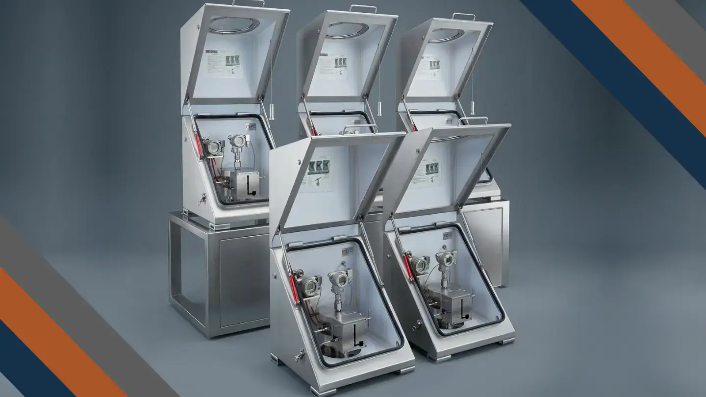
For installations in aggressive environments — offshore, ATEX zones, salt-laden or severe atmospheric conditions — the Interlocking Manifold is available installed inside an IP66 protective enclosure in SS316L stainless steel (painted or bare), providing mechanical and environmental protection for the assembly and connected transmitters.
The IP66 enclosure version is the standard solution for offshore installations (FPSO, FLNG, FSRU) and for skids in ATEX zones.
Self-Regulating Heating Version
In applications with highly viscous fluids or in very low-temperature environments (arctic, deepwater), a version with integrated self-regulating heating within the enclosure is available to prevent freezing of the instrument line and ensure transmitter functionality under all operating conditions. This option has been adopted, among others, in supplies destined for plants in Qatar and FLNG installations.
Certifications: The Reference Regulatory Framework
For those specifying or procuring Interlocking Manifolds in EPC or system integration contexts, certifications are a non-negotiable requirement. The main ones are as follows:
SIL 4 – IEC 61508
SIL 4 certification per IEC 61508 represents the highest level of integrity for safety instrumented systems. Obtained from an accredited third party (TÜV), it guarantees that the hardware architecture and production procedures meet the probabilistic dangerous failure requirements (PFD / PFH) required for the highest safety levels. It is the essential prerequisite for any supply destined for certified HIPPS systems.
PED 2014/68/EU
The Pressure Equipment Directive of the European Union governs the essential safety requirements for pressure equipment placed on the European market. Mandatory for all manifolds with ratings above the exemption limits set by the directive itself.
ATEX 2014/34/EU
The ATEX directive is required for all components intended for installation in zones with a potentially explosive atmosphere (classified as Zone 0, 1, 2 for gases and vapors; Zone 20, 21, 22 for dusts). ATEX marking on the Interlocking Manifold (and its enclosure) is a standard requirement for upstream, offshore, and refinery installations.
IP66
The IP66 protection rating of the enclosure ensures complete protection against dust and against powerful water jets from any direction — a standard requirement for offshore installations and exposed industrial environments.
CRN (Canada) and CU-TR (EAC Countries)
For projects in Canada, CRN (Canadian Registration Number) registration is mandatory for pressure equipment. For the Eurasian Economic Community markets (Russia, Kazakhstan, and EAC countries), CU-TR certification (formerly GOST-R) is required.
Why Choose an Interlocking Manifold Over Traditional Solutions
EPC procurement teams and designers often find themselves comparing the Interlocking Manifold with equivalent solutions assembled from separate components (individual DBB needle valves with external interlock, traditional needle manifolds, etc.). Here are the main differentiating factors:
System integrity: a monolithic body eliminates the joints between separate valves, reducing leak points and simplifying integrity documentation for the process designer.
Unitary certification: the IM is SIL 4 certified as a system, not as a collection of components. For the EPC project manager, this means a single certificate, a single qualified vendor, and a single datasheet to manage in document control.
FAT simplicity: assembly and functional testing take place at the manufacturer’s workshop. The FAT involves the complete assembly, not individual components, reducing on-site testing time and costs.
Traceability and documentation: for projects subject to safety audits (IEC 61511, PSSR, PED), complete traceability of materials, heat treatments, inspection certificates, and hydrostatic test reports in a single supply document is a significant advantage.
Emissions reduction: fewer joints = fewer potential leak sources. This is an increasingly relevant argument for projects subject to fugitive emissions reduction requirements (ISO 15848, API 624).
Case Studies: Real Installations in Critical Contexts
Sakarya Deepwater Field — Black Sea (Turkey)
The Sakarya gas field, Turkey’s largest offshore reserve, required a HIPPS system to ensure operational safety under deepwater high-pressure conditions. In this project — with TPAO as end user and Yokogawa Malaysia as HIPPS system integrator — Indra supplied the Interlocking Manifold as an integral part of the system. The IM was manufactured with all fluid-wetted parts in Super Duplex F55 to ensure maximum corrosion resistance in the aggressive marine environment. The 2oo3 logic was achieved through individual 1oo1 manifolds with flushing rings and butt-weld needles, assembled and tested in-house. Installation took place inside SS316L IP66 enclosures for protection of the offshore units.
FLNG — ZNLG Project for PETRONAS (Malaysia)
For an FLNG vessel destined for liquefied natural gas production, Indra delivered 12 Interlocking Manifolds (4 sets in 2oo3 configuration) as part of a project with Yokogawa Malaysia as HIPPS system integrator, JGC Corporation and Samsung Heavy Industries as EPC contractors, and Petronas as end user. The operating conditions of an FLNG require components certified for marine environments, subject to vibration and varying temperatures, with maximum reliability and minimum maintenance — requirements that the IM series meets in its version with IP66 enclosure and self-regulating heating option.
Qatar Fertilizer Company — QAFCO 7, Ammonia Plant (Qatar)
As part of the QAFCO 7 project — one of the world’s largest ammonia plants — Indra supplied 2oo3 Interlocking Manifolds to Thyssenkrupp, one of the leading process contractors in the chemical and petrochemical industry. The FAT was successfully completed in the presence of the client, confirming compliance with functional and safety requirements, with direct shipment to the QAFCO site.
HIPPS Project in Libya — Orion HIPPS
Indra completed a supply of SIL 4 Interlocking Manifolds for the first HIPPS system built by Orion HIPPS in Libya, also including DBB valves and needle manifolds for instrumentation. This project marked the beginning of a structured collaboration with Orion HIPPS, subsequently confirmed in the construction of the largest HIPPS system ever built, presented in Dubai.
Specification Guide: What to Evaluate During Procurement
If you are specifying or procuring an Interlocking Manifold for a HIPPS system, here are the technical parameters to define before requesting a quotation:
Required voting architecture: 1oo1, 1oo2, or 2oo3 — depends on the SIL target of the overall architecture (calculated by the safety engineer per IEC 61511).
Pressure rating: based on the design pressure of the instrument line. Define ASME or API class and design pressure in bar or psi.
Connections: threaded NPT or flanged ASME B16.5 — verify the requirements of the HIPPS system integrator and project specifications.
Material: evaluate the service (temperature, pH, H₂S content, chloride presence) and select the appropriate material. For offshore environments or those with H₂S, verify compliance with NACE MR0175/ISO 15156.
Seals: PTFE standard; graphite for high temperatures or services with heavy hydrocarbons.
Additional options: flushing ring, butt-weld needles, IP66 enclosure, self-regulating heating, ATEX marking, CRN or CU-TR certification.
Required documentation: datasheet, construction drawings, material certificates (EN 10204 3.1 or 3.2), hydrostatic test reports, TÜV SIL 4 certificate, ATEX certificate, PMI.
Conclusions: The Interlocking Manifold as a Strategic Component for Process Safety
The Interlocking Manifold is not simply a valve component: it is an integrated safety system that conditions the functional integrity of the entire HIPPS system. For EPC teams, system integrators, and skid makers, selecting a SIL 4 certified IM — manufactured with documented-quality DBB needle valves and available in the configurations required by the project — is a decision that directly impacts plant safety, operational continuity, and regulatory compliance.
The integral construction, mechanical interlocking logic, range of materials, and configuration flexibility — from the base version to the modular variant with IP66 enclosure and self-regulating heating — make the Interlocking Manifold the reference solution for any HIPPS architecture in oil & gas, petrochemical, chemical, and LNG applications.
Want to explore the technical specifications or request a custom configuration for your project? Contact the Indra technical team for support in specifying and selecting the most suitable manifold for your application.