In process engineering, measurement reliability depends first and foremost on the quality of the components that isolate, equalize, and vent field instruments. Needle valves and instrumentation manifolds are the silent protagonists of every measurement loop: small in size, critical in function. This technical guide analyzes types, construction features, selection criteria, and applications, with a specific focus on bonnet technology — an element that is often underestimated but decisive for long-term sealing and safety.
Industrial Needle Valves: Operating Principle and Advantages
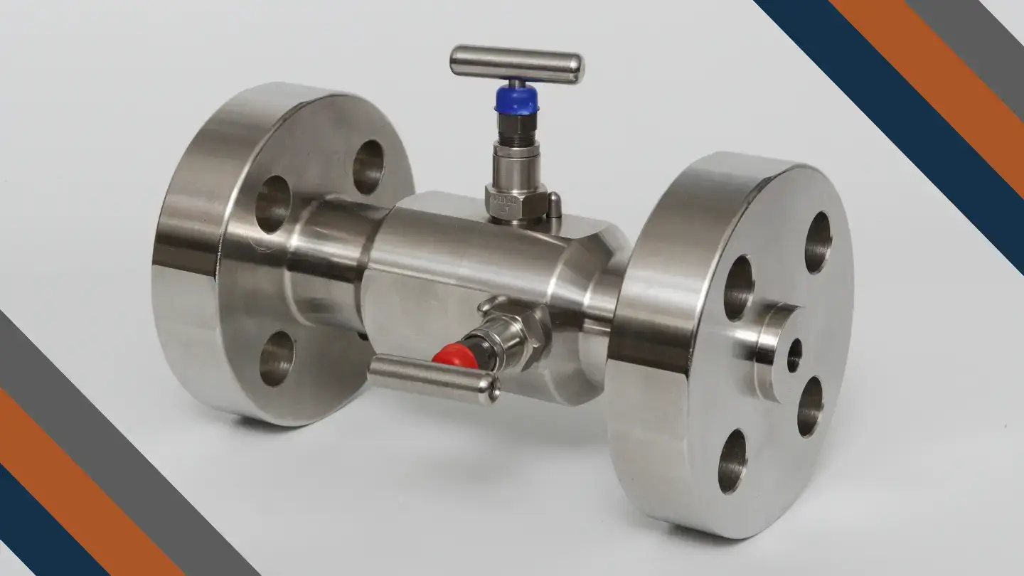
Needle valves are precision components designed for the isolation of pressure instruments in oil & gas, power generation, chemical, petrochemical, and water treatment applications. The operating principle is based on a needle-shaped plug that, as it rotates, moves toward or away from the seat, ensuring precise and repeatable sealing.
Unlike ball valves — optimized for rapid flow shut-off — needle valves excel in applications requiring fine flow control, rigorous sealing under high-pressure conditions, and structural robustness that withstands the cyclic stresses of instrumentation service.
Industrial needle valves are typically manufactured by bar stock machining or forging, ensuring a compact, high-integrity structure free from the internal defects and weld points that characterize assembled constructions.
Bonnet Technology: The Heart of the Seal
The bonnet is the component that houses the stem, ensures external sealing, and protects the actuation mechanism. In the selection of a needle valve, bonnet technology is a primary technical parameter, just as important as the pressure rating or body material.
Key Bonnet Functions
Blow-out Proof Stem: the bonnet design must prevent stem ejection in the event of an incorrect operation or sudden overpressure. This feature is essential for operator safety and must be verified during product qualification.
Non-Rotating Stem Tip: the plug must be free to rotate relative to the stem. When the stem and tip are machined from a single piece, every operation generates friction on the seat, causing progressive wear and loss of seal. The non-rotating tip is therefore a design feature that directly affects the valve’s service life and maintenance frequency.
Multiple sealing points: a well-designed bonnet provides both a primary and a secondary seal, ensuring leak-free performance even in the event of partial degradation of the first barrier. In applications involving hazardous fluids or in contexts with stringent fugitive emission requirements, this feature is critical.
Bonnet Types
Screwed Bonnet: the bonnet is threaded directly into the valve body. It is the simplest and most widespread solution for general applications. The seal relies on the threads and a gasket. It is the standard configuration for services at moderate temperature and pressure.
OS&Y Bonnet (Outside Screw & Yoke): the yoke is a rigid structure attached to the bonnet that supports the stem nut and houses the external thread. When the operator turns the handwheel, the stem moves axially without the threaded section ever coming into contact with the process fluid. This design protects the thread from corrosion, erosion, and contamination, significantly extending the valve’s service life and maintaining smooth operation over time. Also available in lockable and anti-tamper versions for applications requiring access control.
Bolted Bonnet: the bonnet is secured to the body by a bolted bracket. This solution provides maximum resistance at the body-bonnet joint and is preferred for high-pressure, high-temperature, or thermally cyclic services, where maintaining pressure boundary integrity under prolonged mechanical stress is essential.
Extended Bonnet: for cryogenic or high-temperature applications, the extended bonnet acts as a thermal barrier, keeping the stem packing away from the source of extreme heat or cold. The sealing system thus always operates at functional temperatures, regardless of the process fluid temperature. This solution is indispensable for LNG, liquid nitrogen, and thermal services above 300°C.
Bonnet Color Code
In instrumentation manifolds, the bonnet cap color immediately identifies the function of each valve: blue for isolation valves, red for vent valves, green for equalization valves. This visual system reduces the risk of operating errors during field operations, an aspect particularly appreciated in contexts where multiple operators work on the same measurement loop.
Needle Valve Types: Configurations and Applications
In-Line Needle Valve
The in-line needle valve is the basic configuration: the inlet and outlet ports are coaxial (180° apart), allowing the fluid to pass through the valve in a straight line. It is the default solution for isolating pressure instruments installed in line with the piping or impulse tubing.
Available with female-female, male-female, and male-male threaded connections, butt-weld (BW) and socket-weld (SW) ends, it covers a pressure rating range from 6,000 to 15,000 PSI. Versions with an integrated bleed screw add a vent function without additional components, simplifying the instrument loop.
Angle Body Needle Valve
The angle body needle valve deflects flow 90° within the valve body, eliminating the need for a separate 90° elbow or fitting. The operational benefits for skid builders are direct and measurable:
Reduced assembly footprint, with the elimination of one fitting and its associated threaded or welded joint. This means fewer potential leak points, lower weight, and reduced bulk — all relevant parameters for crowded instrumentation panels and skids with tight dimensional constraints. The stem and handwheel orientation is often more accessible to the operator than the in-line version, especially in panel-mounted installations.
Multiport Needle Valve
The multiport needle valve is a specialized solution with more than two connections on the body. It is designed for the economical connection of pressure instruments — standard gauges, pressure transmitters, combined transmitter and local gauge configurations — incorporating vent and drain connections in the valve body without separate components.
It is particularly suitable when a gauge and a transmitter must be installed simultaneously on the same measurement point, or where a dedicated vent connection is required. The bar-stock body with multiple ports reduces the number of fittings and connection points compared to a solution using separate valves and tees.
Instrumentation Manifolds: From Function to Selection
The instrumentation manifold is a monolithic metal block — machined from bar stock or forged — that integrates 2 to 5 valves for controlling flow, pressure, and process fluid measurement. It transforms a series of valves, fittings, and piping into a single compact, certified, high-pressure unit, radically simplifying the instrument loop.
The advantages over traditional assemblies with separate valves are substantial: a drastic reduction in potential leak points (every eliminated connection is one less risk), the monobloc construction that eliminates internal welds and the structural defects typical of assembled constructions, simpler compliance with fugitive emission requirements, and reduced installation and testing time.
Manifolds are available with various connection types — threaded-to-flange or flange-to-flange — seal types (PTFE or graphite), and mounting modes: direct-mount on the actuator or remote via impulse capillary.
2-Valve Manifold
The 2-valve manifold combines one isolation valve and one bleed valve. Its function is to isolate a static pressure instrument — typically a pressure gauge — from the process line and safely vent the residual pressure before removing the instrument for maintenance or replacement.
It is the simplest and most widespread configuration, available in flanged or threaded versions, with direct or remote mounting. Some variants feature an integral swivel adapter that simplifies instrument alignment during installation, and versions with double isolation for more critical applications.
3-Valve Manifold
The 3-valve manifold combines two isolation valves and one equalization valve. It is the standard solution for differential pressure (DP) instruments: the two isolation valves separate the high and low impulse sides from the instrument, while the equalization valve connects the two sides for zero calibration and leak verification.
Available in threaded and flanged versions, and in the “H” format — where the equalization valve is positioned between the two isolation bodies in an H-shaped configuration — which optimizes operational access in confined spaces. Versions with double vents allow independent bleeding of both sides of the differential instrument.
4 and 5-Valve Manifolds
The 4-5 valve manifold is the most complete solution for differential pressure instruments. It combines two isolation valves, one or two vent valves, and one or two equalization valves, ensuring full isolability, independent venting of both sides, and equalization capability across various operating configurations.
It is the reference manifold for critical applications where maximum control is required during commissioning, calibration, and de-commissioning sequences. The 4-valve manifold for non-miscible fluids addresses situations where contamination between the two sides of the instrument — even during equalization — must be absolutely avoided.
Distribution Manifolds and Drain Collectors
Distribution manifolds are high-integrity monolithic blocks designed to split a single utility line (utility gas, instrument air, seal fluid) into multiple independent, individually isolable lines. Machined from a single piece of bar stock — in stainless steel 316 or exotic alloys — with 4 to 12 outlets, they eliminate the network of separate fittings and valves that characterizes traditional solutions. They are essential for isolating gauges, pressure switches, and pressure transmitters on instrumentation panels with many measurement points.
Drain collectors serve the inverse function: they aggregate 10 to 20 individual instrument drain points into a single body, simplifying the discharge system and reducing connections to the collection manifold. Available with straight or 45° inlets to accommodate different installation layouts.
Materials and NACE Compliance: Selection Criteria
The range of materials available for needle valves and instrumentation manifolds covers virtually all application requirements in the oil & gas and petrochemical sectors.
Stainless steel 316/316L is the default material for the vast majority of instrumentation applications, with excellent resistance to general corrosion and wet environments.
Duplex and Super Duplex for services involving chlorides, seawater, or environments with a risk of stress corrosion cracking, typical of offshore applications.
Special alloys — Inconel 625, Alloy 825, Hastelloy, Monel 400, 6Mo, Titanium — for services involving acids, high-concentration H₂S, or other particularly aggressive fluids.
All materials can be supplied in compliance with NACE MR0175 / ISO 15156 for sour gas service, a requirement that is often mandatory in EPC procurement specifications for upstream and midstream applications.
Pressure Ratings and Seal Types
Industrial needle valves cover standard pressure ratings from 6,000 PSI up to 10,000 and 15,000 PSI, with the 15,000 PSI version available with autoclave connection for wellhead applications. The 15,000 PSI rating is also relevant for high-pressure sampling applications and special upstream services.
Available seal options are metal-to-metal — standard and Stellite-coated for abrasive or high-temperature applications — and soft sealing in PTFE or graphite for Class VI (zero leakage) closure at low pressure or moderate temperature.
Special Options and Configurations
Configuration flexibility is a differentiating factor for skid builders and EPC designers who need to integrate instrumentation valves into complex designs. The main available options include:
Locking and anti-tamper devices: locking device, quick locking device, and padlock for controlling operational access in plants with lockout/tagout (LOTO) procedures. The anti-tamper bonnet prevents unauthorized operation without the use of a specific tool.
Fire Safe version: for applications where sealing is required even in the event of fire, in compliance with API 607 and ISO 10497 standards.
Oxygen and hydrogen service: specific configurations with dedicated cleaning, selected materials, and seals compatible with the requirements of these gases.
Fugitive emissions: certification to EN ISO 15848-1 (type approval) and EN ISO 15848-2 (production certification) is available for both needle valves and manifolds, to comply with the increasingly stringent requirements of European and international environmental regulations.
Swivelling connection: facilitates instrument alignment during installation without mechanically stressing the connections.
Painting treatment: for outdoor or offshore environments, as protection against atmospheric corrosion.
Tailor-Made Solutions for Non-Standard Applications
As with ball valves, the ability to develop tailor-made solutions is a relevant competitive factor in the needle valves and instrumentation manifold segment for more complex EPC projects.
Among the most significant examples of custom configurations are: 2-valve manifolds with integral compression fitting (eliminating an additional joint on the impulse circuit); 2 and 5-valve manifolds for 15,000 PSI ratings for ultra-high-pressure wellhead applications; needle valves with OS&Y bonnet and bolted bracket for combined high-pressure and high-temperature services; and 7-valve hybrid manifolds for complex measurement configurations where a standard solution is not applicable.
The tailor-made process involves structured collaboration with the client’s technical team — from requirements analysis through prototype qualification — with the goal of delivering solutions that not only meet project specifications but exceed them in terms of operational reliability.
In-House Testing and Product Certifications
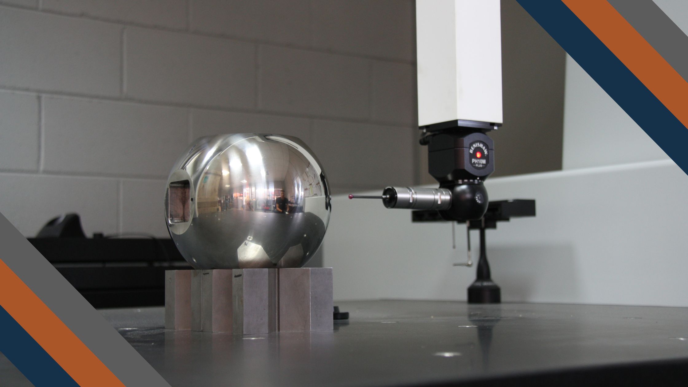
For qualifying a needle valve and manifold supplier, procurement teams must verify internal testing capabilities. The fundamental tests that a structured manufacturer should perform with their own staff and equipment include: fugitive emission testing (production and prototype), TAT test, PR2F test, cryogenic test, high temperature test, high pressure gas test up to 15,000 PSI, and NDT (PMI, UT, DP, MP, and HRC tests).
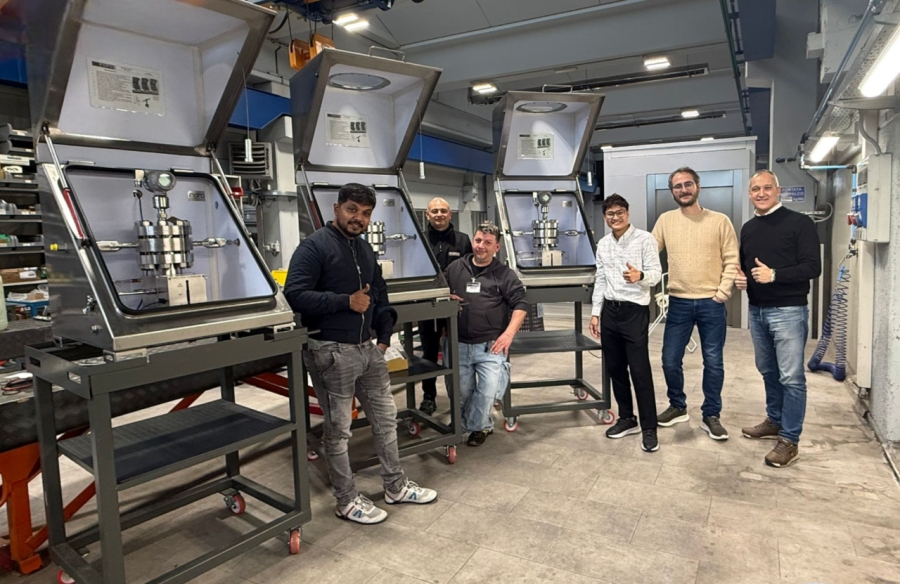
The in-house availability of a climatic chamber for PR2F and TAT tests, a cryogenic tank, and a bunker for high-pressure gas testing ensures full traceability of the qualification process and reduces dependence on external laboratories, with positive impacts on delivery lead times.
The product certifications that a qualified supplier must hold include: Fire Safe ISO 10497, API 607 and API 6FA, Fugitive Emission ISO 15848-1 and 15848-2, PED 2014/68/EU, ATEX 2014/34/EU, CRN for the Canadian market, and CU-TR for EAC countries.
Selection Guide: The Right Questions to Ask
For procurement teams and EPC designers, the correct selection of needle valves and manifolds starts with a systematic analysis of key parameters:
Required function in the measurement loop: simple isolation (2 valves), differential measurement with equalization (3 valves), differential measurement with full isolation and double vent (4-5 valves), multi-point distribution (distribution manifold).
Pressure rating: the working pressure of the process fluid, including upset cases and hydrostatic tests, determines the minimum valve rating. For ratings above 6,000 PSI, always verify product availability in the specific material and connection combination.
Connection type and size: NPT or ISO thread, sizes ¼”, 3/8″, ½”, ¾”, 1″, flanged connections for the instrument interface. The centreline (port spacing on the instrument side) must match the standard of the installed transmitter.
Mounting: direct mount on the instrument or remote mount with impulse lines. Direct mount eliminates impulse lines and potential leak points, and is the preferred solution for clean, non-viscous fluids where there are no freezing or precipitation issues.
Bonnet type: screwed for standard services, OS&Y for high pressure and ease of maintenance, bolted for high temperature and thermal cycling, extended for cryogenic or high-temperature services.
Seal type: PTFE for standard applications, graphite for high temperature or services with fluids that attack PTFE, metal-to-metal for high pressures and abrasive services.
Certification requirements: NACE MR0175 for sour service, ISO 15848 for fugitive emissions, fire safe for classified areas, ATEX for potentially explosive atmospheres.
Conclusions
The selection of needle valves and instrumentation manifolds requires technical knowledge that goes well beyond reading a catalogue. Bonnet technology, seal options, pressure ratings, and available configurations are interconnected variables that must be analyzed based on specific service conditions and applicable regulatory requirements.
A manufacturer with a fully in-house process — from design to machining through final testing with their own equipment — offers concrete guarantees of quality, traceability, and delivery schedule compliance that are essential for EPC project success. The ability to develop tailor-made solutions, finally, is the factor that distinguishes a technical partner from a simple catalogue supplier.
For support in selecting the most suitable manifold or needle valve for your application, contact our technical team.